


Toshiba T6400DXC Capacitor Replacement
This is a follow up on the Toshiba T6400DXC luggable PC. There were quite a lot of leaking capacitors on the mainboard and in the LCD panel. Here is an overview of what needed to be replaced.
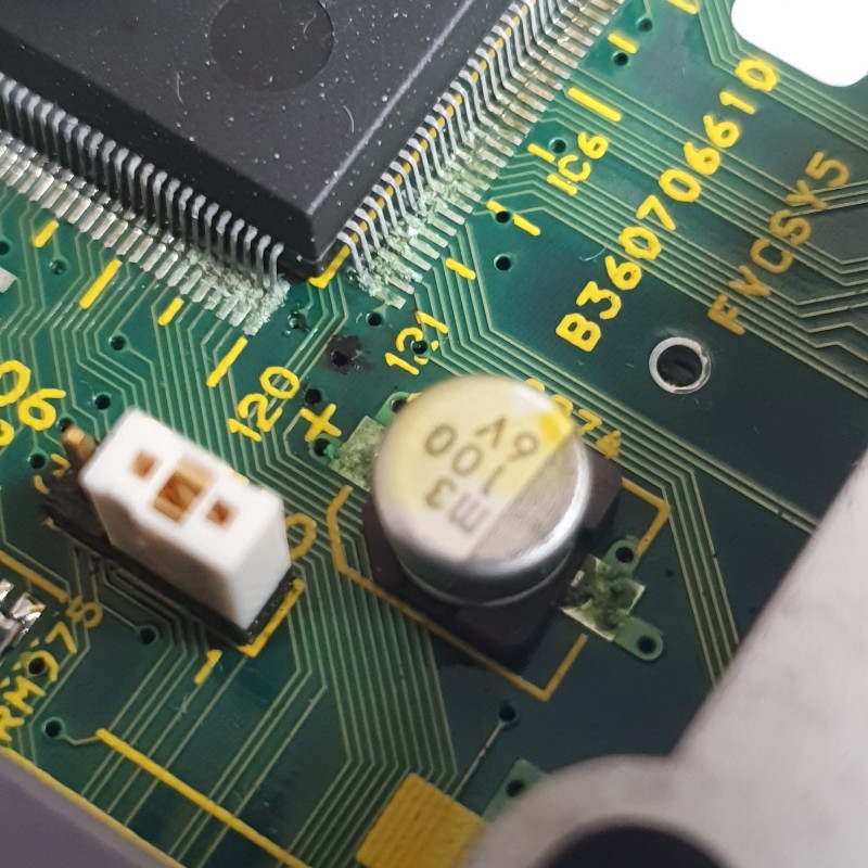
An example of a leaky SMD capacitor on the mainboard:
Here is a list of capacitors on the mainboard:
|------|-----------|--------|
| ID   | Value     | Type   |
|------|-----------|--------|
| C448 | 10uF 6.3V | Square |
| C969 | 10uF 6.3V | Square |
| C903 | 33uF 16V  | Square |
| C421 | 47uF 6.3V | Square |
| C444 | 47uF 6.3V | Square |
| C45  | 47uF 6.3V | Square |
| C443 | 100 6V    | SMD    |
| C905 | 100 6V    | SMD    |
| C912 | 100 6V    | SMD    |
| C968 | 100 6V    | SMD    |
| C974 | 100 6V    | SMD    |
| ?    | 100 6V    | SMD    |
| C446 | 47 16V    | SMD    |
| C447 | 47 16V    | SMD    |
| C77  | 47 16V    | SMD    |
| C970 | 47 16V    | SMD    |
| C971 | 47 16V    | SMD    |
| C973 | 47 16V    | SMD    |
| ?    | 10 50V    | SMD    |
|------|-----------|--------|
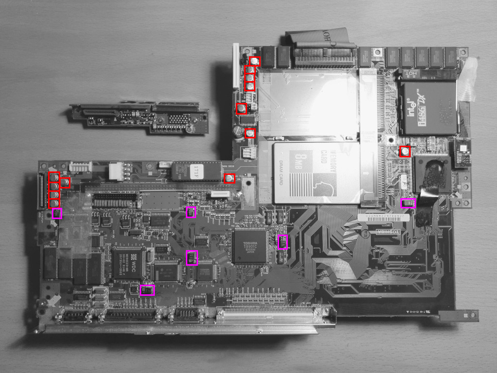
Here is a photo of the mainboard capacitor locations, the red ones are SMD and the purple ones the square ones:
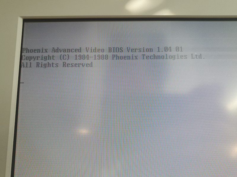
A working LCD panel will have white text on a black background. With leaking capacitors the LCD panel looks "inverted" with black text on a white background like this:
Here is a list of capacitors on the LCD panel which are located across several locations:
|----------|-----|-----------|---------------------|
| Location | ID | Value | Type, Height x Diam |
|----------|-----|-----------|---------------------|
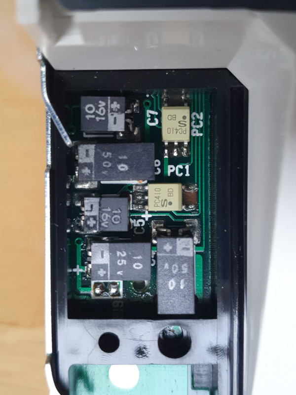
| Cluster | C7 | 10uF 16V | Square |
| Cluster | C5 | 10uF 16V | Square |
| Cluster | C4 | 10uF 25V | Square |
| Cluster | C6 | 10uF 50V | Square |
| Cluster | C3 | 10uF 50V | Square |
|----------|-----|-----------|---------------------|
| Edge | ? | 3,3uF 16V | Square |
| Edge | ? | 3,3uF 16V | Square |
|----------|-----|-----------|---------------------|
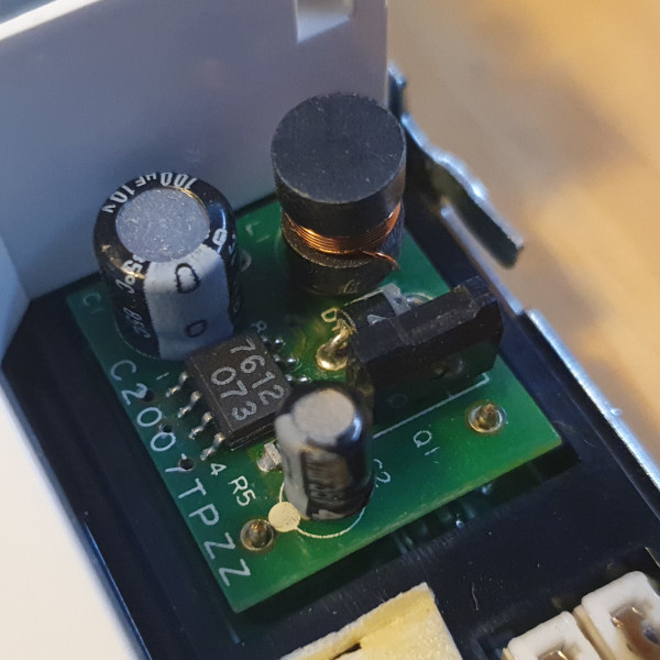
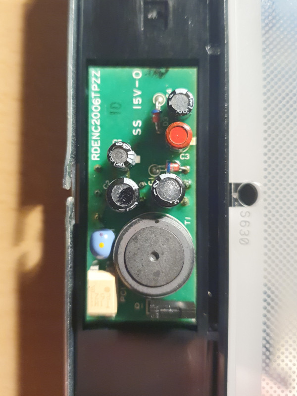
| C2006 | C1 | 22uF 16V | Radial, 7mm x 5mm |
| C2006 | C2 | 22uF 16V | Radial, 7mm x 5mm |
| C2006 | C3 | 4,7uF 35V | Radial, 7mm x 4mm |
| C2006 | C4 | 10uF 16V | Radial, 7mm x 4mm |
| C2006 | C5 | 10uF 16V | Radial, 7mm x 4mm |
|----------|-----|-----------|---------------------|
| C2007 | C1 | 100uF 10V | Radial, 7mm x 6mm |
| C2007 | C2 | 4,7uF 25V | Radial, 6mm x 4mm |
|----------|-----|-----------|---------------------|
| Main | CA | 100uF 25V | Radial, 9mm x 6mm |
| Main | CB | 100uF 10V | Radial, 9mm x 5mm |
| Main | CC | 47uF 16V | Radial, 9mm x 5mm |
| Main | CD | 47uF 16V | Radial, 9mm x 5mm |
| Main | CE | 47uF 16V | Radial, 9mm x 5mm |
| Main | CF | 47uF 25V | Radial, 9mm x 5mm |
|----------|-----|-----------|---------------------|
The "cluster" before replacement:
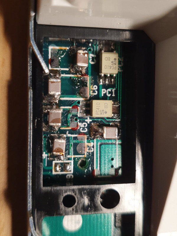
The "cluster" after replacement, with MLCC equivalents:
The C2006 sub-board before replacement:
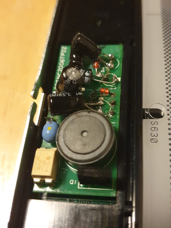
The C2006 sub-board after replacement, note that the new capacitors needs to be bent in certain directions to fit:
The C2007 sub-board before replacement, removed:
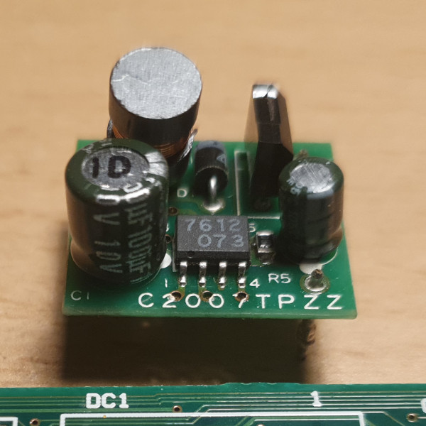
The C2007 sub-board after replacement, installed: