


Gould 1604 Oscilloscope Repair
Warning: Be careful when working with power supplies, they can contain dangerous voltages even when in powered off state.
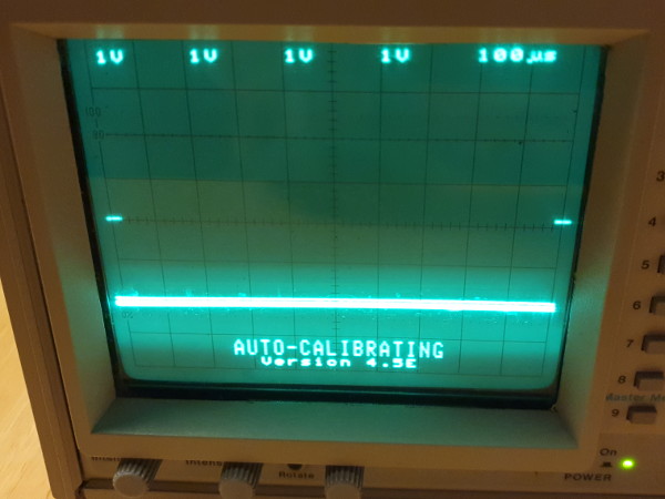
I have gotten hold of a Gould DRO 1604 oscilloscope from 1989. It would power on, but the display was severely distorted and looked like this:
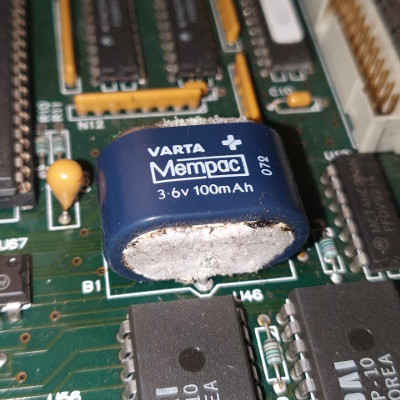
I cracked open the case and first of all removed a leaking battery, which is not related to the display problem, but important to fix as soon as possible:
Luckily there is a service manual available for this particular oscilloscope, which helps a lot in giving troubleshooting tips and places to measure. I first discovered that pin 4 of U803 (the Y DAC chip) had -3.3V but the service manual said it should be either -2.8V or -4.2V, depending on the "dot joining" state. This led me to Q811 (a MOSFET controlling the "dot join") which had a strange voltage of -3.41V on it's gate, where it should have been either 0V or -5V. According to the circuit diagram the gate of Q811 is pulled by a resistor connected to the -12V power rail.
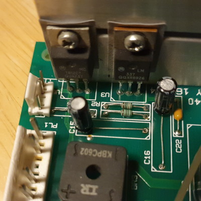
I measured the -12V rail, and this was only around -11V which is too low. This rail is controlled by a LM377T linear regulator, which is adjusted by a set of resistors and capacitors. I checked the three associated resistors R1, R2 and R16 and they all had the correct values. However, the two capacitors C15 and C16 had correct capacitance but horrible ESR value of 23 and 33 ohms.
Here are the two bad capacitors, with blue casing:
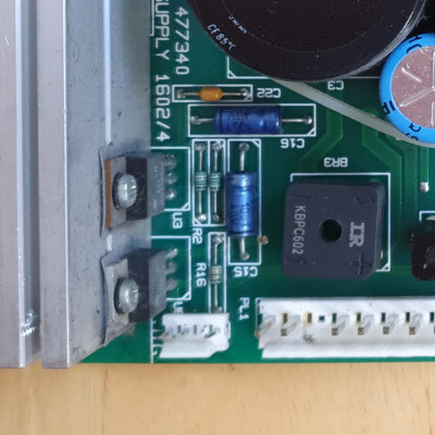
Which i promptly replaced with new ones:
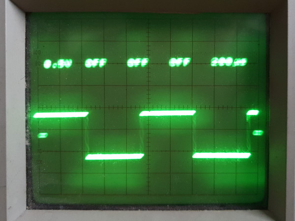
This fixed the -12V power rail, which now measures around actual -12 volts, and the display is now working: