


Booting DOS from PS/2 BASIC
I have a old standalone motherboard from an IBM PS/2 Model 80. The PS/2 systems have a different kind of floppy connector and floppy drive, so one cannot simply connect a regular PC floppy drive without doing some hardware modifications. But fortunately, most of the PS/2 systems have IBM Cassette BASIC in ROM chips on the motherboard and will boot that in case everything else fails.
Someone else has already managed to boot some software from BASIC, so I took it a step further and was able to boot DOS as well. My work is based on the previous Serial Port Floppy Drive Emulation tricks to emulate the floppy drive over the COM1 port. The assembly program presented here will attempt boot a floppy image. Unfortunately I have not been able to boot the reference disk yet...
Once booted into BASIC, it is technically possible to input the complete program by hand (by keyboard):
1 data 233,157,0,184,192,7,142,192,49,219,184,1,2,185,1,0,49,210
2 data 205,19,234,0,124,0,0,251,128,250,0,117,90,128,252,2,116,5
3 data 128,252,3,117,74,83,81,82,80,80,80,232,76,0,136,224,232,71
4 data 0,136,200,232,66,0,136,232,232,61,0,136,208,232,56,0,136,240
5 data 232,51,0,90,48,246,184,0,2,247,226,137,193,88,128,252,3,116
6 data 11,232,49,0,38,136,7,67,226,247,235,9,38,138,7,232,18,0
7 data 67,226,247,88,90,89,91,48,228,248,202,2,0,234,121,0,121,0
8 data 82,186,248,3,238,186,253,3,236,36,32,132,192,116,249,90,195,82
9 data 186,250,3,236,36,14,60,4,117,246,186,248,3,236,90,195,186,251
10 data 3,236,12,128,238,186,248,3,176,12,238,186,249,3,176,0,238,186
11 data 251,3,236,36,127,238,186,250,3,176,6,238,186,251,3,176,3,238
12 data 186,249,3,236,12,1,238,49,192,142,216,250,232,0,0,88,91,45
13 data 210,0,137,198,184,48,0,142,192,191,0,0,185,157,0,46,138,4
14 data 38,136,5,70,71,226,246,62,161,76,0,38,163,119,0,62,161,78
15 data 0,38,163,121,0,62,199,6,76,0,22,0,62,140,6,78,0,49
16 data 192,62,163,0,4,251,180,9,176,33,183,0,179,4,185,3,0,205
17 data 16,180,0,205,22,234,0,0,48,0
99 def seg=1984:a=0:for i=0 to 297:read j:poke a+i,j:next:call a
However, it is very easy to make a mistake and this work is very tedious.
Instead it's a lot better to chain-load the program using the same method from the GitHub link.
The steps are as follows, assuming you are on a Linux box:
1) Make sure that the serial port on your system is set correctly:
stty -F /dev/ttyS0 9600 raw
2) Enter and run the chain-loader in BASIC on the PS/2 system:
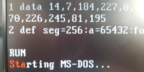
1 data 14,7,184,227,0,153,137,215,205,20,185,19,1,180,2,205,20,158,120,249,252,170,226,245,81,195
2 def seg=256:a=65432:for i=0 to 25:read j:poke a+i,j:next:call a
3) Send the assembled program directly through the serial port:
cat sfdboot.bin > /dev/ttyS0
4) Start the serial port floppy drive emulator with a bootable image:
./serialfd -d /dev/ttyS0 -a floppy.img
5) If everything went well, there should be three red exclamation marks on the PS/2 system, press any key to commence the booting from the emulated image.
In the case of booting MS-DOS it should look something like this:
Here is the assembly code, assembled with NASM as follows: nasm sfdboot.asm -fbin -o sfdboot.bin
org 0x0 ; Position independent.
bits 16
cpu 8086

COM1_BASE equ 0x3f8
COM1_THR  equ COM1_BASE + 0 ; Transmitter Holding Buffer
COM1_RBR  equ COM1_BASE + 0 ; Receiver Buffer
COM1_IER  equ COM1_BASE + 1 ; Interrupt Enable Register
COM1_FCR  equ COM1_BASE + 2 ; FIFO Control Register
COM1_IIR  equ COM1_BASE + 2 ; Interrupt Identification Register
COM1_LCR  equ COM1_BASE + 3 ; Line Control Register
COM1_LSR  equ COM1_BASE + 5 ; Line Status Register
COM1_DLL  equ COM1_BASE + 0 ; Divisor Latch Low Byte
COM1_DLH  equ COM1_BASE + 1 ; Divisor Latch High Byte

RESIDENT_SEGMENT equ 0x0030 ; Bootstrap stack area.

section .text
start:
  jmp main

resident_code_start:
  ; Setup ES:BX to point at bootloader address 07C0:0
  mov ax, 0x07C0
  mov es, ax
  xor bx, bx

  ; Read VBR into bootloader memory area:
  mov ax, 0x0201
  mov cx, 0x0001
  xor dx, dx
  int 0x13

  ; Jump to bootloader:
  jmp 0x0:0x7C00

int13_interrupt:
  ; Allow other interrupts:
  sti

  ; Check if accessing drive 0 (A:)
  ; If not, then jump to original interrupt instead.
  cmp dl, 0
  jne original_int13

  ; Only operation 0x02 (Read) and 0x03 (Write) are forwarded.
  ; The rest are bypassed directly and returns OK.
  cmp ah, 2
  je _int13_interrupt_ah_ok
  cmp ah, 3
  jne _int13_interrupt_end
_int13_interrupt_ah_ok:

  ; Save registers:
  push bx
  push cx
  push dx

  ; Save sectors and operation information on stack for use later:
  push ax
  push ax
  push ax

  ; Register AL already set.
  call com_port_send
  mov al, ah
  call com_port_send
  mov al, cl
  call com_port_send
  mov al, ch
  call com_port_send
  mov al, dl
  call com_port_send
  mov al, dh
  call com_port_send

  ; Retrieve sector information (stack AL) into DL register:
  pop dx
  xor dh, dh

  mov ax, 512
  mul dx ; DX:AX = AX * DX
  mov cx, ax

  ; Determine receive (Read) or send (Write) from operation (stack AH):
  pop ax
  cmp ah, 3
  je _int13_interrupt_send_loop

_int13_interrupt_recv_loop:
  call com_port_recv
  mov [es:bx], al
  inc bx
  loop _int13_interrupt_recv_loop
  jmp _int13_loop_done

_int13_interrupt_send_loop:
  mov al, [es:bx]
  call com_port_send
  inc bx
  loop _int13_interrupt_send_loop

_int13_loop_done:

  ; Retrieve sector information (stack AL) as sectors handled:
  pop ax

  ; Restore registers:
  pop dx
  pop cx
  pop bx

_int13_interrupt_end:
  ; AL register will have same value as upon entering routine.
  xor ah, ah ; Code 0 (No Error)
  clc ; Clear error bit.
  retf 2

original_int13:
  jmp original_int13:original_int13 ; Will be overwritten runtime!

; Send contents from AL on COM1 port:
com_port_send:
  push dx
  mov dx, COM1_THR
  out dx, al
  mov dx, COM1_LSR
_com_port_send_wait:
  in al, dx
  and al, 0b00100000 ; Empty Transmit Holding Register
  test al, al
  jz _com_port_send_wait
  pop dx
  ret

; Return contents in AL on COM1 port:
com_port_recv:
  push dx
_com_port_recv_wait:
  mov dx, COM1_IIR
  in al, dx
  and al, 0b00001110 ; Identification
  cmp al, 0b00000100 ; Enable Received Data Available Interrupt
  jne _com_port_recv_wait
  mov dx, COM1_RBR
  in al, dx
  pop dx
  ret

resident_code_end:

main:
  ; Set Baudrate on COM1 to 9600, divisor = 12:
  mov dx, COM1_LCR
  in al, dx
  or al, 0b10000000 ; Set Divisor Latch Access Bit (DLAB).
  out dx, al

  mov dx, COM1_DLL
  mov al, 0xc
  out dx, al

  mov dx, COM1_DLH
  mov al, 0
  out dx, al

  mov dx, COM1_LCR
  in al, dx
  and al, 0b01111111 ; Reset Divisor Latch Access Bit (DLAB).
  out dx, al

  ; Disable and clear FIFO on COM1, to put it in 8250 compatibility mode:
  mov dx, COM1_FCR
  mov al, 0b00000110 ; Clear both FIFOs.
  out dx, al
  ; NOTE: Not tested what happens if this is run on an actual 8250 chip...

  ; Set mode on COM1 to 8 data bits, no parity and 1 stop bit:
  mov dx, COM1_LCR
  mov al, 0b00000011 ; 8-N-1
  out dx, al

  ; Enable interrupt bit on COM1:
  mov dx, COM1_IER
  in al, dx
  or al, 0b00000001 ; Enable Received Data Available Interrupt
  out dx, al

  ; Interact directly with IVT:
  xor ax, ax
  mov ds, ax ; Data Segment now 0000
  cli ; Disable Interrupts

  call get_ip
get_ip:
  pop ax ; IP
  pop bx ; CS
  sub ax, (get_ip - resident_code_start)
  mov si, ax ; "resident_code_start" now in SI.

  ; Copy the code to a new resident area using CS:SI -> ES:DI
  mov ax, RESIDENT_SEGMENT
  mov es, ax
  mov di, 0
  mov cx, (resident_code_end - resident_code_start)
_copy_to_resident_area:
  mov byte al, [cs:si]
  mov byte [es:di], al
  inc si
  inc di
  loop _copy_to_resident_area

  ; Save old interrupt handler:
  ; ES = RESIDENT_SEGMENT
  mov ax, [ds:0x4c]
  mov word [es:original_int13 - resident_code_start + 1], ax
  mov ax, [ds:0x4e]
  mov word [es:original_int13 - resident_code_start + 3], ax

  ; Overwrite with new interrupt handler:
  ; ES = RESIDENT_SEGMENT
  mov word [ds:0x4c], (int13_interrupt - resident_code_start)
  mov word [ds:0x4e], es

  ; Zero out COM1 port address in BDA to avoid DOS interference:
  ; DOS can set baudrate to 2400 at startup, which will cause issues.
  xor ax, ax
  mov word [ds:0x400], ax

  sti ; Enable Interrupts

  ; Indicate on screen "Ready for Loading" after key press:
  mov ah, 0x9  ; Write character and attribute at cursor position.
  mov al, 0x21 ; Character = '!'
  mov bh, 0    ; Page Number = 0
  mov bl, 0x4  ; Color = Red
  mov cx, 0x3  ; Number of Times = 3
  int 0x10

  ; Read any key press:
  mov ah, 0x0  ; Read keystroke.
  int 0x16

  ; Jump to new resident area:
  jmp RESIDENT_SEGMENT:0
The code is also uploaded to the serialfd GitHub repository in case of future changes and improvements.